BT560 series tool inspectors are usually used in tool factories, tool grinding centers, and tool procurement inspection departments. They can efficiently and accurately inspect the geometric elements and their accuracy of various types of tools. These elements are usually important factors related to the cutting performance of tools, and their accuracy standards are generally accepted by the automotive industry.
The functions of BT560E Tool Tester
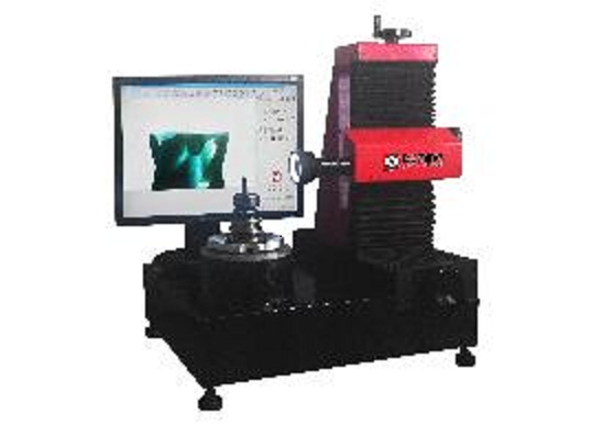
The mechanical structure of BT-560 tool tester is simple. The tool angle is adjusted by a rotating axis. The high-resolution CCD camera is fixed on two straight axes to adjust the observation position. The geometric shape of the tool is measured by image analysis software, because these geometric shapes may affect the overall cutting performance of the tool. This is the focus of the tool tester.
Detection theory
BT560 tool tester can be divided into pixel measurement and grating measurement from measuring principle. Pixel measurement is based on the display pixels of an image (an instantaneous image) as the basis of measurement and calculation, so in the case of different magnification, the "occupied" pixels per unit length (e.g. 0.002mm) are different, so it is necessary to calibrate for different magnification ( that is determining the number of pixels per unit length). This method is flexible and convenient to operate, but it can only be measured in a single field of view with a small measurement range. Its measurement accuracy is affected by the display resolution and calibration accuracy. It is suitable for occasions where the measurement accuracy is not high.
Grating measurement is based on the position of camera coordinates (X and Z-Axis) and the angle of the tool rotation axis (B axis). One of the methods is to overlap the vertical straight line segment (or horizontal line segment) of the cross line with the edge of the cutter's contour. At this time, the corresponding grating reading is cleared to zero, and the handwheel is rotated to move the corresponding linear axis so that the straight line segment coincides with the other edge of the cutter's contour. At this time, the value displayed by the grating is the linear size. Another method is to take the center point of the cross line as the "mouse pointer" and collect the key points on the cutter image for drawing, so as to achieve the purpose of measurement.
Note that the display window moves the tool image instead of the cross cursor, and the calculation is based not on the pixel but on the raster coordinate display value. The measurement method has high accuracy, because it does not need calibration, and the measurement results have nothing to do with display resolution. In addition, the grating measurement range is large, not limited by a single field of view, but can be observed by the motion of the guide rail. The geometric line segments and arcs are drawn by this method will "stick" to the image with the movement of the image, which is suitable for measuring large cutters whose images are beyond the field of view.